Mechanical glockenspiel
Mechanical glockenspiel
Several tasks and iterations to bring the glockenbox into fruition!
First version, the John Smith glockenspiel
First version, the John Smith glockenspiel
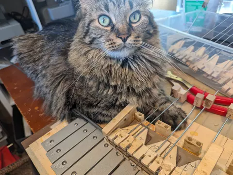
The Topsy 3 design calls for an air-operated glockenspiel, with leather over air pockets to push the strikers. I just couldn't get it to work. I might try again sometime, because it's nice to save a few magnets for other projects. Here Korben Dalek is helping in the design and construction.
Glockenbox mock-up
Glockenbox mock-up
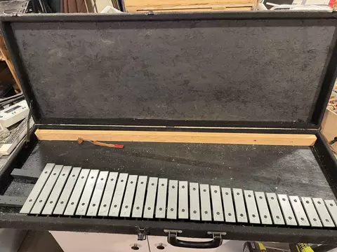
Here we have the initial layout of the glockenspiel bars inside the hard case. I measured clearances, etc, made the mounting rails, and found I had enough room for two more bars! Since the driver board has 32 outs, I figured this would be perfect. I fabricated the two lower bars.
Hippie hair hammer heads
Hippie hair hammer heads
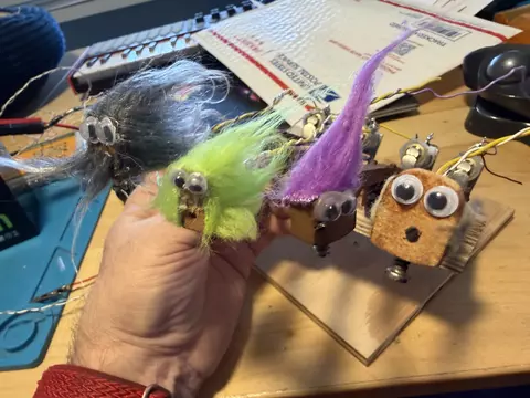
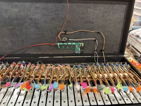
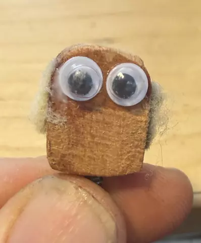
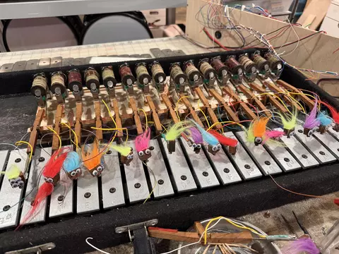
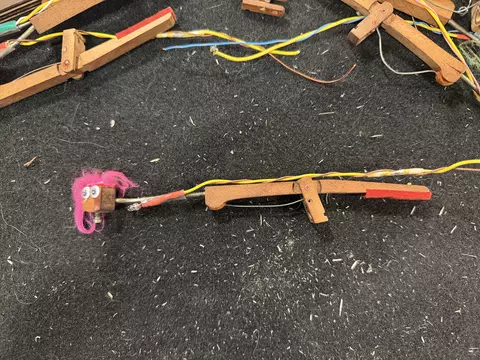
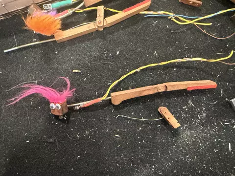
This adds so much fun to the Glockenbox! The strikers are made from piano damper levers and flanges. I removed the damper felt and rotate the heads to use the set screws to strike the glockenspiel bars, then I thought they really needed googley eyes. Then they looked a little bald. I added colored plush material for hair, and the glockendudes were born!
I created 32 individual unique striker heads, some of them have names. This one kind-of looks like Jean Luc Picard to me.
Horizontal glock strikers
Horizontal glock strikers
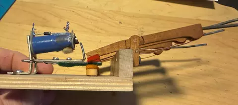
I wanted to share a close‑up of the hammer mechanism for my glockenspiel.
There are two levers involved in the action. The first lever is attached directly to the electromagnet frame. When the magnet is energized, it pulls this metal lever upward. That motion lifts the butt end of a second lever—a wooden seesaw lever—which has a felt pad at the butt end and the hammer head mounted on the opposite end. When the butt end goes up, the hammer end goes down and strikes the bar.
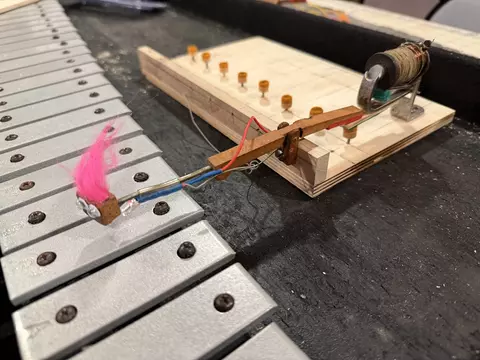
The bumpers supporting the butt end of the wooden levers are salvaged from an old piano. They’re mounted on screws in countersunk holes, which lets me fine‑tune the lever height simply by twisting the screws up or down.
The wooden lever assemblies are made from piano damper arms. I had to work out the geometry carefully and cut each lever to exactly the right length so the magnet would have enough mechanical advantage to drive the hammer effectively.
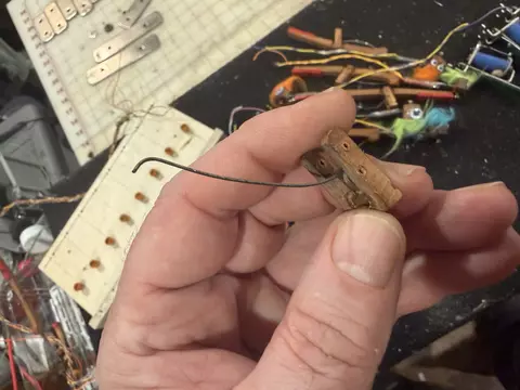
I removed the original damper arm springs and fabricated new ones. Each damper arm flange has two pins: a wooden pin that passes through the loop of the spring to hold it in place, and a separate metal pin that acts as the axle, allowing the arm to pivot on the flange. To install the new springs, I had to un‑pin the flanges, seat the springs correctly, and then re‑pin everything. I experimented with metal pin diameters to allow free motion without introducing side‑to‑side wobble.
I also experimented with different spring shapes and materials to get exactly the right action and response. And then I repeated this entire process for each of the 32 notes.
I decided to mount groups of the strikers onto plates to make it easier to build and maintain. Here you can see the magnet, capstan, rail, damper lever and flange, striker head, and the LED wiring.
In progress
In progress
Here's a view of the hammer mechanisms mounted onto plywood plates and set in place in the instrument case that will become the glockenbox
This is the way we make the springs
This is the way we make the springs
🎶This is the way we make the springs, make the springs, make the springs!🎶
Here's an overview of how I fabricated the striker action return springs. The striker actions were made from salvaged upright piano dampers. It was very handy that they had return springs, but those springs were too stiff and brittle for our purposes. Here's a picture of damper arms with the original springs:
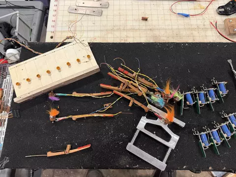
Here's several damper arms all ready for their new springs. That tool that looks like a grip exerciser is a piano flange pinning tool. You can also see an action-mounting plate all ready with its capstans and several modified pallet magnets all ready for a set of eight striker actions.
Fabricating and installing the new spring
Fabricating and installing the new spring
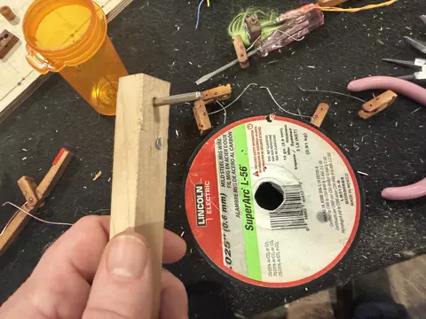
I tested several different materials for the new springs and I ended up using 0.025" MIG wire. It's nice and pliable and can hold its shape when it's positioned to distribute force well.
I made a spring winding tool with a block of maple and a piano balance rail pin and wrapped three times starting at 6:00 and ending at a 2:00 position.
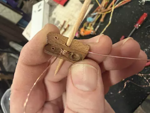
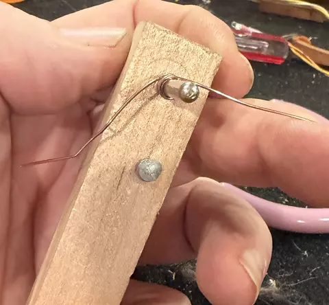
Next I threaded the standing end of the spring into the retaining hole and used a toothpick to pin it in place.
I trimmed the wire below the flange, glued the toothpick into place and clipped off the excess.
Removing the old spring
Removing the old spring
The first thing I did was unpin the flange so I could remove the spring.
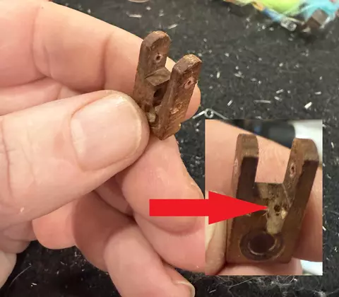
Here's a closeup of the original spring. They were held in place with some rolled bushing cloth. You can see the tiny hole for seating the spring drilled into the flange.