Bass idiophone designing
Bass idiophone designing

Just when you thought it was safe to do housework, here comes yet another distraction! What if I could make a bass (or baritone) instrument to augment my musical range? Here's some articles on working out a bass xylophone thing.
Onboard bonker idea
Onboard bonker idea
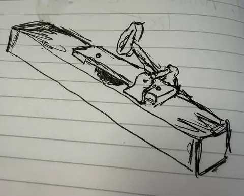
I was thinking that if I mounted the bonker mechanism directly on the resonator pipe, the hammer shaft would need to be pretty long to accommodate most of them. So I came up with the idea of a hammer arm pivoting on risers that straddle the tone bar. I'd have to engineer the actuator, but the possibilities are pretty vast.
Comments
Coppy describes this as: a …
Coppy describes this as:
This appears to be a quick pen sketch on lined notebook paper. The drawing shows a long rectangular wooden-looking beam or housing viewed in perspective, running diagonally from the lower right toward the upper left.
Mounted on top of the beam is a mechanical assembly consisting of:
- A hinged lever or arm attached near the center.
- A pivot point indicated by a round fastener or pin.
- A small circular or oval component above the lever that resembles a wheel, knob, roller, or pulley.
- A spring-like or coiled element near the right side of the mechanism.
- Additional shaded areas that suggest moving parts, bearings, or hardware mounted within a slot in the beam.
The beam itself has darkened ends and rough hatching marks, giving the impression of wood grain or shading. The mechanism appears hand-drawn and conceptual rather than dimensioned or engineered.
The overall impression is that of a simple mechanical device, possibly:
- A latch or trigger mechanism,
- A valve actuator,
- A hammer action for a musical instrument,
- A clamp or locking assembly,
- Or another lever-operated mechanical linkage.
Because the sketch is schematic and lacks labels, dimensions, or context, I cannot determine its exact purpose with confidence. However, the key visual features are a long rectangular base, a pivoting lever, a circular component above the lever, and what appears to be a spring-assisted linkage.
Given your history of building mechanical musical instruments and organ actions, my first impression is that it could be a rough concept sketch for a hammer, pallet, or actuator mechanism, but that is only a possibility rather than something visible in the drawing itself.
- Log in to post comments
I added AI for helping with…
I added AI for helping with alt text for images. AI thinks this is: Pencil sketch of a mouse in a mousetrap on lined notebook paper
- Log in to post comments
Wow. Okay. I asked Coppy …
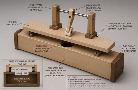
Wow. Okay. I asked Coppy (Copilot) to generate a 3d image of this, and after plenty of discussion it came up with this monstrosity:
- Log in to post comments
Single bass bars
Single bass bars
Using Sonor singles as the design, we're ideating bass bars using 2" x 3/4" maple and salvaged organ pipes as resonator boxes.
These bass bars use wide maple tone bars coupled to short, sealed wooden resonators. Instead of tuning pipes to exact acoustic lengths, we scale the cross‑section to maintain strong low‑frequency response while keeping the resonators compact and workshop‑friendly. Bar widths and pipe bores graduate smoothly to maintain consistent timbre across the range.
- The tone bars are hard maple, ¾″ thick, widths graduated from 4″ (C2) to 2″ (F4).
- Bar lengths are starting blanks; final tuning is achieved by undercutting and small end trims.
- Pipe lengths are chosen for practical handling and broad‑band resonance, not strict half‑wave tuning.
- Nodal offset is the distance from each end of the tone bar where it's supported (22-23% of the bar length).
- The sound hole is centered under the bar’s midpoint, with a ½″ air gap between bar and pipe.
- All resonators are sealed at both ends; any flue or mouth openings on salvaged pipes must be fully blocked.
Undercut the bars gingerly as needed.
Image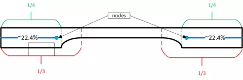 NameIdeal tone bar shape
| Note | Freq (Hz) | Bar width | Bar length (start) | Nodal offset | Pipe internal size | Pipe length | Hole center | Hole diameter |
|---|---|---|---|---|---|---|---|---|
| C2 | 65.41 | 4″ | 26½″ | 5¾″ | 4″ × 4″ | 60″ | 30″ | 2¼″ |
| C♯2 | 69.30 | 3⅞″ | 26″ | 5¾″ | 3⅞″ × 3⅞″ | 58″ | 29″ | 2⅛″ |
| D2 | 73.42 | 3¾″ | 25½″ | 5⅝″ | 3¾″ × 3¾″ | 56″ | 28″ | 2⅛″ |
| D♯2 | 77.78 | 3⅝″ | 25″ | 5½″ | 3⅝″ × 3⅝″ | 54″ | 27″ | 2″ |
| E2 | 82.41 | 3½″ | 24½″ | 5⅜″ | 3½″ × 3½″ | 52″ | 26″ | 2″ |
| F2 | 87.31 | 3½″ | 24″ | 5¼″ | 3½″ × 3½″ | 48″ | 24″ | 2″ |
| F♯2 | 92.50 | 3¼″ | 23½″ | 5⅛″ | 3¼″ × 3¼″ | 46″ | 23″ | 1⅞″ |
| G2 | 98.00 | 3¼″ | 23″ | 5″ | 3¼″ × 3¼″ | 44″ | 22″ | 1⅞″ |
| G♯2 | 103.83 | 3″ | 22½″ | 5″ | 3″ × 3″ | 42″ | 21″ | 1⅞″ |
| A2 | 110.00 | 2⅞″ | 22″ | 4⅞″ | 2⅞″ × 2⅞″ | 40″ | 20″ | 1¾″ |
| A♯2 | 116.54 | 2¾″ | 21½″ | 4¾″ | 2¾″ × 2¾″ | 38″ | 19″ | 1¾″ |
| B2 | 123.47 | 2⅝″ | 21″ | 4⅝″ | 2⅝″ × 2⅝″ | 36″ | 18″ | 1¾″ |
| C3 | 130.81 | 2½″ | 19½″ | 4⅜″ | 2½″ × 2½″ | 34″ | 17″ | 2¼″ |
| C♯3 | 138.59 | 2⅜″ | 19″ | 4¼″ | 2⅜″ × 2⅜″ | 33″ | 16½″ | 2⅛″ |
| D3 | 146.83 | 2⅜″ | 18½″ | 4⅛″ | 2⅜″ × 2⅜″ | 32″ | 16″ | 2⅛″ |
| D♯3 | 155.56 | 2¼″ | 18″ | 4″ | 2¼″ × 2¼″ | 31″ | 15½″ | 2″ |
| E3 | 164.81 | 2¼″ | 17½″ | 3⅞″ | 2¼″ × 2¼″ | 30″ | 15″ | 2″ |
| F3 | 174.61 | 2¼″ | 17″ | 3¾″ | 2¼″ × 2¼″ | 29″ | 14½″ | 2″ |
| F♯3 | 185.00 | 2⅛″ | 16½″ | 3⅝″ | 2⅛″ × 2⅛″ | 28″ | 14″ | 1⅞″ |
| G3 | 196.00 | 2⅛″ | 16″ | 3½″ | 2⅛″ × 2⅛″ | 27″ | 13½″ | 1⅞″ |
| G♯3 | 207.65 | 2⅛″ | 15½″ | 3⅜″ | 2⅛″ × 2⅛″ | 26″ | 13″ | 1⅞″ |
| A3 | 220.00 | 2″ | 15″ | 3¼″ | 2″ × 2″ | 25″ | 12½″ | 1¾″ |
| A♯3 | 233.08 | 2″ | 14½″ | 3⅛″ | 2″ × 2″ | 24″ | 12″ | 1¾″ |
| B3 | 246.94 | 2″ | 14″ | 3⅛″ | 2″ × 2″ | 23″ | 11½″ | 1¾″ |
| C4 | 261.63 | 2″ | 13½″ | 3″ | 2″ × 2″ | 22″ | 11″ | 1⅝″ |
| C♯4 | 277.18 | 2″ | 13″ | 2⅞″ | 2″ × 2″ | 21″ | 10½″ | 1⅝″ |
| D4 | 293.66 | 2″ | 12⅞″ | 2⅞″ | 2″ × 2″ | 20″ | 10″ | 1½″ |
| D♯4 | 311.13 | 2″ | 12½″ | 2¾″ | 2″ × 2″ | 19½″ | 9¾″ | 1½″ |
| E4 | 329.63 | 2″ | 12″ | 2⅝″ | 2″ × 2″ | 19″ | 9½″ | 1½″ |
| F4 | 349.23 | 2″ | 11¾″ | 2⅝″ | 2″ × 2″ | 18½″ | 9¼″ | 1½″ |
Tuning workflow (in inches)
For each note:
- Cut bar. Use the target length from the range above, add ~½ inch extra.
- Mount on supports. Place supports at 22–23% of length from each end (measure in inches).
- Tune bar. Undercut underside to lower pitch.
- Tiny end trims (¹⁶–⅛ inch) to raise pitch if needed.
- Build pipe.
- Cut off the sound-making end square and seal it.
- Cut pipe to theoretical length. If the pipe has a stopper, add 4" to the length to take advantage of it.
- Cut the sound hole into the pipe.
- Place the bar over the hole, then trim length or move stopper to match bar pitch.
- Fine tune by adjusting the rail height or hole diameter until the bar stays clear but the pipe adds that bass bloom.