Double‑Barrel magnet blaster
Double‑Barrel magnet blaster

This article documents a compact, mirrored, dual‑channel high‑side driver designed for 12 V pallet magnets using the IRF9520 P‑channel MOSFET. Each channel includes a gate network, flyback protection, indicator LED, and a manual test button. The design is optimized for clarity, repairability, and modularity.
Overview
Each channel uses an IRF9520 P‑channel MOSFET as a high‑side switch, meaning the MOSFET sits between the +12 V supply and the magnet. Pulling the gate low turns the magnet on; releasing the gate allows the pull‑up resistor to turn the MOSFET off.
The circuit includes:
- A 10 kΩ gate pull‑up (default OFF)
- A 100 Ω gate series resistor (clean switching)
- A 1N4001 flyback diode across the magnet
- A channel‑colored LED + resistor for visual indication
- A momentary test button that fires the magnet without external control
- Mirrored Blue and Green channels for easy layout and troubleshooting
This driver is suitable for 12 V pallet magnets up to ~2 A.
Parts List (per channel)
Semiconductors
- 1 × IRF9520 P‑channel MOSFET (TO‑220)
- 1 × 1N4001 flyback diode
- 1 × LED (Blue or Green)
- 1 × LED resistor (1 kΩ for Blue, 1.5 kΩ for Green)
Gate Network
- 1 × 10 kΩ gate pull‑up resistor
- 1 × 100 Ω gate series resistor
User Interface
- 1 × Momentary test button (normally open)
Connectors / Wiring
- 2‑pin terminal for magnet (+ and −)
- 2‑pin terminal for control input (signal and ground)
- +12 V and GND rails on the board
How the Circuit Works
High‑Side Switching
The IRF9520 is wired with:
- Source → +12 V
- Drain → Magnet +
- Magnet − → Ground
When the gate is pulled low, the MOSFET turns on and supplies +12 V to the magnet.
Gate Network
- A 10 kΩ pull‑up keeps the MOSFET off by default.
- A 100 Ω series resistor protects the gate and reduces switching noise.
- The control input or test button pulls the gate low to activate the magnet.
Flyback Protection
A 1N4001 diode is placed directly across the magnet:
- Cathode → Magnet + (MOSFET drain)
- Anode → Magnet − (ground)
This clamps the inductive kick when the magnet turns off.
Indicator LED
The LED and its resistor connect from +12 V to the MOSFET drain.
When the MOSFET turns on and the drain drops toward ground, the LED lights.
Assembly Instructions
1. Prepare the Power Rails
- Establish a +12 V rail and a ground rail on the board.
- Keep these rails clean and well‑defined for both channels.
2. Install the IRF9520 MOSFETs
For each channel:
- Pin 1 (Gate) → Gate network
- Pin 2 (Drain) → Magnet + and diode cathode
- Pin 3 (Source) → +12 V rail
Ensure the MOSFETs face the same direction for mirrored layout.
3. Build the Gate Network
For each channel:
- Solder a 10 kΩ resistor from Gate → +12 V (pull‑up).
- Solder a 100 Ω resistor from Gate → Control Input.
- Connect the test button between Gate → Ground.
4. Add the Flyback Diode
Across the magnet terminals:
- Banded end (cathode) → MOSFET drain / magnet +
- Non‑banded end (anode) → Ground / magnet −
5. Install the Indicator LED
- LED anode → +12 V
- LED cathode → LED resistor → MOSFET drain
Use:
- 1 kΩ for Blue LED
- 1.5 kΩ for Green LED
6. Connect the Magnet Terminals
Each channel gets a 2‑pin terminal:
- Pin 1 → MOSFET drain (magnet +)
- Pin 2 → Ground (magnet −)
7. Connect the Control Inputs
Each channel gets a 2‑pin control header:
- Signal → 100 Ω gate resistor
- Ground → Board ground
8. Final Checks
- Verify MOSFET orientation
- Confirm diode polarity
- Ensure gate pull‑ups are connected to +12 V
- Press test buttons to confirm each magnet fires
- Check LEDs light during activation
Diagram
here's an ASCII representation of this circuit:
                   +12V RAIL
                      |
        -------------------------------------
        |                                   |
   [IRF9520]                             [IRF9520]
   Blue MOSFET                           Green MOSFET
   (P‑channel)                           (P‑channel)
        |                                   |
   Source (S)                           Source (S)
        |                                   |
        +-------------+12V------------------+
        |
   Drain (D) ---------------------.     Drain (D) ---------------------.
        |                         |          |                         |
        |                     [MAGNET]       |                     [MAGNET]
        |                     Blue +         |                     Green +
        |                         |          |                         |
        |                    (to GND)        |                    (to GND)
        |                         |          |                         |
        |                     [DIODE]        |                     [DIODE]
        |                 1N4001 (across)    |                 1N4001 (across)
        |
   Gate (G) <---100Ω--- Control In      Gate (G) <---100Ω--- Control In
        |                                   |
       10kΩ                                 10kΩ
        |                                   |
       +12V                                 +12V
        |                                   |
   [TEST BUTTON]                        [TEST BUTTON]
        |                                   |
       GND                                 GND

   LED + Resistor                      LED + Resistor
   (Blue channel)                      (Green channel)
   +12V ---[LED]---[1kΩ]--- Drain      +12V ---[LED]---[1.5kΩ]--- Drain
Performance Notes
- The IRF9520 is not a logic‑level MOSFET, but at 12 V it fully turns on when the gate is pulled to ground.
- At 2 A magnet current, the MOSFET dissipates roughly 1–2 W, which is acceptable for short organ note durations.
- The mirrored layout makes troubleshooting straightforward: if one channel works, the other should match it exactly.
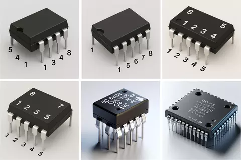
Imaginary ICs
Imaginary ICs
I was designing a circuit with Copilot and it just couldn't get the components to connect correctly, so I asked Coppy to draw me a picture of a 6N138, an 8-pin DIP. It invented these.