Lignoutron build log
Lignoutron build log
Who doesn't want a self-playing xylophone? Here's some of the work I did to make this thing a reality.
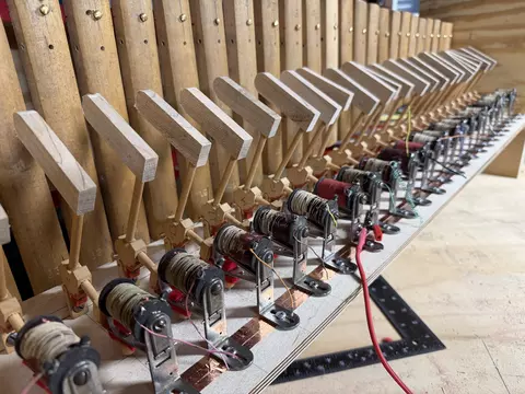
This image shows the hammers and actuators lined up and all ready to strike those bars!
Artist's conception
Artist's conception
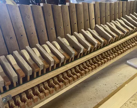
I originally thought it would be fun to give this instrument some amount of registration, so I built it with alternating hard and soft hammers, with the idea of sliding the rail side to side to select which hammer was used.

The idea was the hammers were skinny enough so sliding the rail back and forth would allow the actuator to lift only one of the hammers. I gave up on this idea because I just couldn't imagine having enough force to move that heavy rail fully-populated.
Bass xylophone test bars
Bass xylophone test bars
Guide: Cutting and Preparing A2, E3, and C4 Test Bars From One 5″ × 48″ Maple Board
1. Board Breakdown
Material: ¾″ × 5″ × 48″ quarter‑sawn hard maple
Goal: Produce three representative test bars (low, mid, high) with minimal waste.
Rip the board into:
- Two strips at 2″ width (48″ long each)
- One strip at 1″ width (48″ long, used for practice pieces)
Crosscuts:
- From Strip 1:
- 24″ → A2 blank
- 18″ → E3 blank
- 6″ → practice offcut
- From Strip 2:
- 12″ → C4 blank
- Remaining 36″ → spare long blank or additional tests
- Strip 3 (1″):
- Use for resonator mouth blocks, drilling tests, or narrow high‑note experiments
This layout wastes almost nothing and gives you a full low/mid/high test set.
2. Test Bar Blank Dimensions
A2 Test Bar
- Blank size: 24″ × 2″ × ¾″
- Node locations: 5.4″ from each end
- Node hole size: 3/16″ clearance
- Mounting: Top nodes only (screws + O‑rings), bottom nodes floating
E3 Test Bar
- Blank size: 18″ × 2″ × ¾″
- Node locations: 4.0″ from each end
- Node hole size: 3/16″ clearance
- Mounting: Same as A2
C4 Test Bar
- Blank size: 12″ × 2″ × ¾″
- Node locations: 2.7″ from each end
- Node hole size: 3/16″ clearance
- Mounting: Same as A2
3. Starting Undercut Dimensions
These are safe starting cuts: deep enough to tune easily, shallow enough to avoid overshooting.
A2 Undercut
- Length: 8″ (centered)
- Width: 1.25″
- Depth: 0.20″ (leave ~0.55″ thickness)
E3 Undercut
- Length: 6″
- Width: 1.00″
- Depth: 0.18″ (leave ~0.57″)
C4 Undercut
- Length: 3.5″
- Width: 0.75″
- Depth: 0.15″ (leave ~0.60″)
General undercut notes:
- Shape: rectangular trench with rounded corners
- Tune mostly with undercut until within ~20 cents
- Final tuning: trim bar length, not depth
- Avoid thinning the bar below ~0.60″ except at the very center
4. Resonator Starting Lengths
All resonators are quarter‑wave tubes, tuned by trimming the bottom end.
Top end is capped with a side‑hole mouth placed behind the lower node of the bar.
A2 Resonator
- PVC diameter: 2″
- Starting length: 31–32″
- Side‑hole: near cap, aligned with lower node
E3 Resonator
- PVC diameter: 1.5″
- Starting length: 23″
- Side‑hole: near cap, aligned with lower node
C4 Resonator
- PVC diameter: 1.25″
- Starting length: 14″
- Side‑hole: near cap, aligned with lower node
Side‑hole size: ⅓–½ of tube ID
Gap between bar and resonator mouth: ⅛″–¼″
5. Mounting Hardware
Recommended:
- #6 round‑head wood screws
- 3/16″ clearance holes in the bar
- Leather punching + O‑ring stack under screw head
- Screws tightened only enough to prevent wobble
- Bottom nodes left completely floating
This produces a clean free‑free mode and excellent resonator coupling.
6. Summary Table
NoteBlank SizeNode DistanceUndercut (L × W × D)Resonator (PVC × Length)
A2
24″ × 2″ × ¾″
5.4″
8″ × 1.25″ × 0.20″
2″ × 31–32″
E3
18″ × 2″ × ¾″
4.0″
6″ × 1.00″ × 0.18″
1.5″ × 23″
C4
12″ × 2″ × ¾″
2.7″
3.5″ × 0.75″ × 0.15″
1.25″ × 14″
Ideation
Ideation
This is what I got and a bit of deciding how to build the machine.
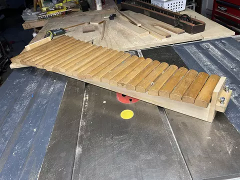
Initial build-up
Initial build-up
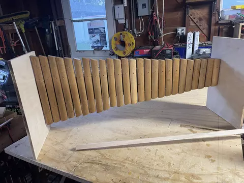
Here's an initial assembly of the instrument with its resonator box suspended between plywood boards.
Original xylophone
Original xylophone
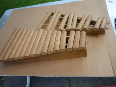
I got this very cheap on eBay. It's clearly not very pretty, but all the bars are there. I salvaged the maple bars and built a whole new instrument for them.
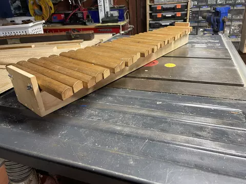
Resonator box
Resonator box
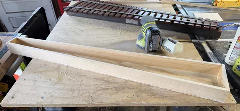
I copied my Deagan orchestrion xylophone's resonator box hoping to get a good sound out of these bars and took no account for the correct nodes on the bars. The box is made mainly out of salvaged organ pipe lumber.
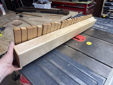
Xylophone in suspense!
Xylophone in suspense!
One of the early iterations. I tried suspending the bars above the resonator box with wire, as an "improvement" to the string suspension it had originally. I learned a whole bunch from this experiment, including the idea that I painted myself into a corner laying the bars out with so little room between them. I was building the frame from scratch so there was no reason to try to squish it all together.